The structural analysis software RFEM 6 is the basis of a modular software system. The main program RFEM 6 is used to define structures, materials, and loads of planar and spatial structural systems consisting of plates, walls, shells, and members. The program also allows you to create combined structures as well as to model solid and contact elements.
RSTAB 9 is a powerful analysis and design software for 3D beam, frame, or truss structure calculations, reflecting the current state of the art and helping structural engineers meet requirements in modern civil engineering.
Do you often spend too long calculating cross-sections? Dlubal Software and the RSECTION stand-alone program facilitate your work by determining section properties of various cross-sections and performing a subsequent stress analysis.
Do you always know where the wind is blowing from? From the direction of innovation, of course! With RWIND 2, you have a program at your side that uses a digital wind tunnel for the numerical simulation of wind flows. The program simulates these flows around any building geometry and determines the wind loads on the surfaces.
Are you looking for an overview of snow load zones, wind zones, and seismic zones? Then you are in the right place. Use the Geo-Zone Tool to determine quickly and efficiently snow loads, wind speeds, and seismic data according to ASCE 7‑16 and other international standards.
Would you like to try out the capabilities of the Dlubal Software programs? You have the opportunity to do so! The free 90-day full version allows you to thoroughly test all our programs.
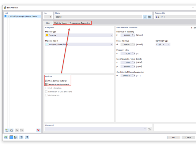
After opening a material from the library, you can use the "User-Defined Material" option to access the material properties.
You can also use the options to control the dependence of the modulus of elasticity due to the temperature.
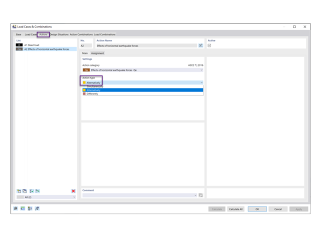
RFEM default setting assumes the orthogonal combination of the X and Y directions. To apply the Independent Directional procedure, go to the Actions tab and change the action type from Simultaneously to Alternatively for Qe (Image 01).
Next, go to the Design Situations tab and select Edit Combination Wizard. In the Standard Options tab, deactivate the “Include orthogonal combinations” option (Image 02).
As shown under the Load Combinations tab, the orthogonal COs are no longer listed (Image 03).
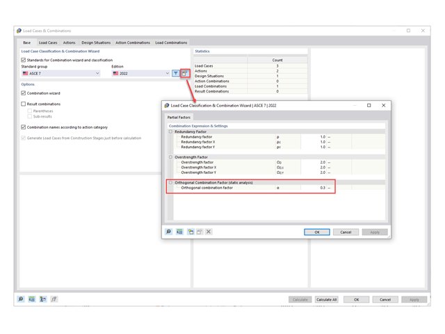
1) The default orthogonal combination factor is set to 0.3 (30%). This value can be changed by going to Edit Parameters of Edition in the Load Cases & Combinations (Image 1)
2) Under the Load Cases tab, create the seismic load cases in the X and Y directions with Qe as the Action Category. Specify the direction under the Additional Settings tab (Image 2)
3) Under the Design Situations tab, select the Edit Combination Wizard button. In the Standard Options tab, make sure that the Include orthogonal combinations option is activated (Image 3)
4) The generated COs including the orthogonal combination factor are listed in the Load Combinations tab (Image 4)
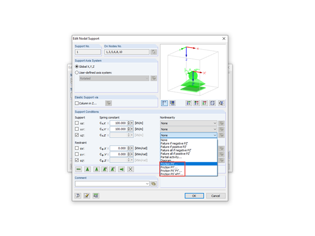
In both RFEM and RSTAB, it is possible to consider friction for the translation at nodal support.
You can select from different options that take into account the different directional components. For example, the friction force for the z‑direction can be calculated from just the y‑component or just from the x‑component, but also from both together or even from the addition of both forces.
In addition to the friction coefficient, you can define the spring constant. It determines the behavior of the support before reaching the maximum friction force or the transition from static friction to sliding friction. The higher the value of the spring constant, the less the support can deform before it changes to the sliding friction.
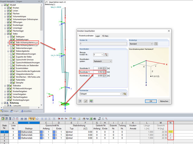
The reason that a continuous inclination cannot be applied is usually due to the fact that the members differ in their orientation. However, the imperfections are based on the directions of the local member axes.
You can see this clearly if you display the local member axis systems in the Project Navigator.
The problem with the different orientation of the local z-axis is due to the general position of the members. You can see this, for example, in Column "N" in Window 1.7 (RFEM 1.17). If a member is inclined in space, the position of local axes y or z is automatically defined by RFEM/RSTAB. The z-axis lies in space in such a way that the Z-component of the directional arrow always points in the positive global Z-direction in relation to the global coordinate system. The y-axis is then obtained according to the right-hand rule.
The inclined position of the member can usually be explained by a nodal inaccuracy. This is also the case in the attached example, as can be seen from the Y-coordinate of Node 1 (0.002 m instead of 0.000 m).
Furthermore, it is possible to change the tolerance for considering a member as vertical. This setting can be made under "Tools" → "Regenerate Model".
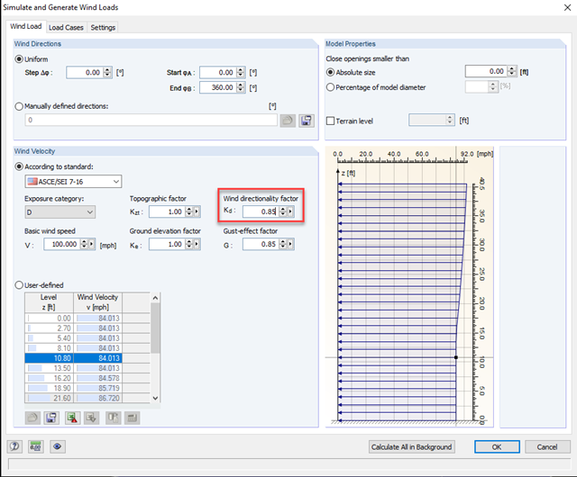
The wind directionality factor (Kd) from the ASCE 7‑16 Sect. 26.6 is considered in the ASCE 7‑16 wind load profile or RWIND Simulation calculation and can be adjusted manually by the engineer. The wind directionality factor (Kd) can be considered in RWIND Simulation by modifying the factor under the wind velocity profile settings before running RWIND Simulation in RFEM.
This factor for various structure types can be determined from table 26.6‑1 from the ASCE 7‑16 [1].